Friday, December 08, 2006

More Projects Installed

I spent most the week assembling custom windows which just involves opening boxes and following arcane instructions describing how to screw the things together. It is not very interesting or rewarding from a craft point of view. Oh well. You can't make cupolas and arched jambs every week, I suppose.

This afternoon after lunch, I did drive out to the west end to find a house where a couple of my past projects have been installed. You may recall the big PVC entrance head and pilasters from a couple of months ago. Below, you can see it installed. It's weird how the scale of this kind of thing changes based on its setting. In the shop, this assembly seemed massive. In place, one would hardly notice it.


The curved staircase I made back in the early summer is installed in the same house. I was shocked to find it in such abominable condition on the job site. The picture below was taken the day the staircase left the shop.


...and this one was snapped at the site about two hours ago. As I look at this, I shudder to think of the time I spent carefully filling brad holes and sanding, and sanding, and sanding. Maybe it'd be better if I didn't go visit these things after they're installed!

Monday, December 04, 2006

Arched Jamb Heads Complete

This afternoon I finished a set of five poplar arched jamb heads with wide trim and key blocks. Below is the largest of the heads.


One of my coworkers built box columns which will wrap rough openings on the job site. The heads I made will then sit on top of the columns. You'll get a sense of what I mean in the picture below.


Three of the heads were the same size. There was one wider head and one narrower one as you can see. I wonder why people always want this kind of thing at a paint-grade level of finish? I think it would be fun to make some of these from walnut or cherry.


I had never really built anything like these before. The project involved a great deal of radius work on the shaper; the trim that you see on the face of each arch above is comprised of six curved elements in addition to the straight runs and the key block. You can get a sense of what I mean in the picture below which shows the pieces before they were assembled.


I don't know yet what my next project will be, but you'll hear about it when I find out. In the meantime, if you're reading this and you'd like any more detail about this or any of the past projects, please email me and I'll very happily respond. Likewise, if you do similar work--or indeed any kind of craft--I'd love to hear about it and see some pictures, too.

Friday, December 01, 2006

Cupolas Installed!

After work today I drove out to the east end to see if the cupolas had been installed. They had been, and the general contractor was kind enough to climb three or four ladders with me so we could go have a look. Here are a few pictures of the cupolas where I hope they'll be for a long time to come.


Tomorrow I plan to post extensively about the arched door jambs I'm wrapping up at the beginning of next week.

Sunday, November 26, 2006

Arched Jambs and Raised Panel Doors

Since finishing that set of cupolas, I haven't had anything really major to sink my teeth into. I did make three frame and panel doors last week; they were a rush job, and pretty big, but I got them done in two days. They're pictured below. Other than that I've been working on a set of five arched door jambs with lots of trim, key blocks and whatnot. I'll post more about those soon.


Here is one of the three completed white pine frame and panel doors. These were all about five feet tall and ranged in size from 24" to 36" wide. In the absence of our shaper man, we're trying to switch everything we can to the router table. I think it's the right move. Using a shaper for little beads and whatnot is like using a sledgehammer to squash a mosquito. We got a router bit to raise the panels for these doors, and it worked like a champ. I made two passes, and even the cross-grain cuts were nice and clean.


I mentioned that I'm working on several arched jambs. The picture above shows a set I did about six months ago. When I arrived at the shop, arches like this were done by stacking and butt-jointing strips of white pine, assembling them, then bandsawing and sanding the curve. That's more or less the way that curved drawer fronts have traditionally been made. I find this system inefficient and think it produces an unreasonable amount of waste. Clear white pine is not cheap these days. So, when I get a work order for curved jambs, I'm doing them differently.


Specifically, I'm using bending ply and forms. In this picture you see the beginning of the concave half of a set of bending forms for one of the arches I'm making. I use a router with an arc-cutting jig to cut the radius into a blank of cheap ply material. I then attach that arched blank to a second rectangular blank, bandsaw about 1/16" away from the line of the arc, then flush-trim the second arc so it's a perfect reproduction of the first. I install the blocks between them, cover the whole thing with 3/8" bending luan, then get started on the convex half (not pictured).

More to come in future posts.

Sunday, November 05, 2006

Cupolas (Finally) Fly the Coop

Well, the cupolas are done. I didn't post for a while because things got kind of crazy at the shop a few weeks ago. One of my coworkers sustained a completely hideous injury, and it was all I could do to show up and get my work done for a while thereafter. I'm going to try to recreate some of the more interesting steps in the cupolas' construction between my last post and the present.

Click here to see a video of the cupolas leaving the shop.


Here's a mockup of the basic structure I designed for the roof framing. The central, short octagonal column provided a convenient way to join the rafters together. The cleat you see on the left-hand side of the rafter was glued to the column, and the rafter was glued to the cleat. That way, if the steel fasteners ever rust away, there should still be a good glue connection between the parts.


This photo shows the final central columns with cleats attached. I thought they ended up looking like gears.


I needed a 59 1/2 degree cut on one end of the rafters, but since my cutoff saw only goes to 55 degrees, I had to make the jig you see above. It basically added the additional 4 1/2 degrees and provided a length stop as well.


I figured out how much overhang the roof bases were meant to have over the face of the posts and marked that distance at each corner of the bases. I used a sharpie for one of these marks so you could see what I was talking about.


I registered my mark on the underside of the bases with their proper location with regard to the post faces. I didn't spend much time photographing this step because it didn't seem all that interesting. Suffice it to say that the roof bases were secured to the posts with long lag bolts.


With the roof bases secured to the posts, I was ready to begin installing the rafters as you can see above.


Here are the completed cupola frames.


Once framing was complete, the next step was to make and install the louvers. I'm not going to go into the louver-making process right now because it was so mind-crushingly dull that it pains me to think about it. Here are a few relevant details, though. There were 17 louver slats per side, 8 sides per cupola, and 5 cupolas. That makes 680 slats. Each slat was connected to its frame with four stainless steel screws. That's 2720 screws that I had to install. B-O-R-I-N-G! Somebody, please get me an apprentice, and soon!


The final steps were sheathing the roofs and applying the facing trim. Making the roofing panels was probably interesting enough to merit documentation, but by then I'd reached the point of just wanting to get these things done, so I didn't drag the camera out every few minutes.

Monday, October 09, 2006

Cupola Roofs

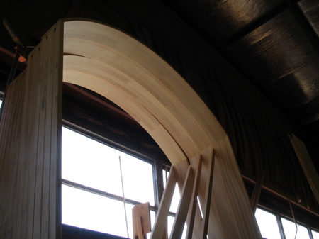
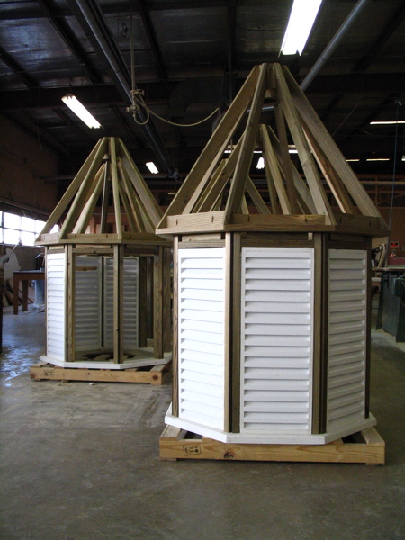
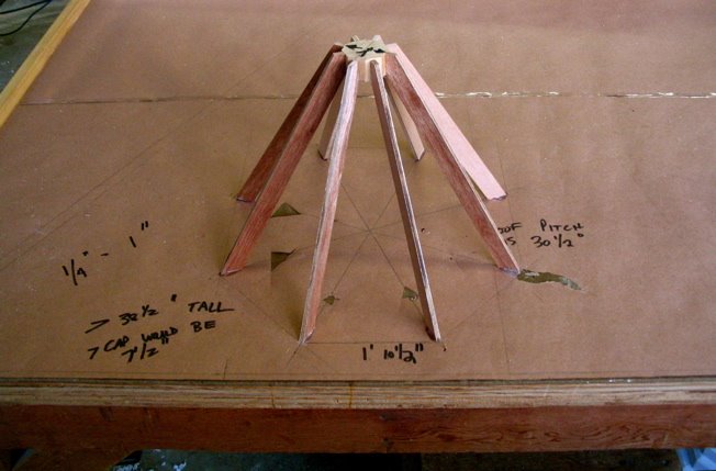
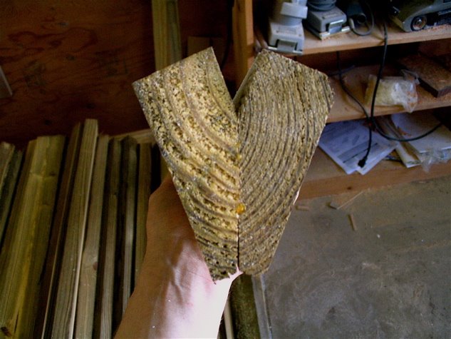
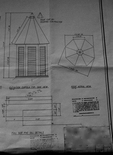
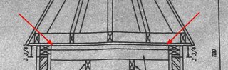
The next step on the cupolas was to make the octagonal bases for the roofs, indicated by red arrows in the drawing below. Unlike the pressure-treated plywood bottoms in the bases, I wanted these to have some real heft, so I made them from 2 x 8's.


The first step was to once again calculate the octagon dimension I needed. It would be entirely too boring to detail the computations I underwent to determine this fact, but I will say that the online octagon calculator my boss found has indispensable throughout this project. If you're interested, you can see it here. Suffice it to say that I determined the length I needed from each face of the octagon and crosscut my stock to that dimension (with 22 1/2 degree angles at each end so that they'd form the shape I needed when put together).


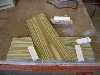
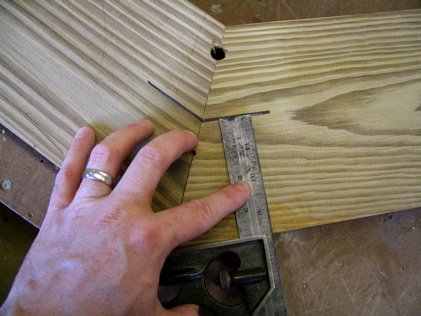
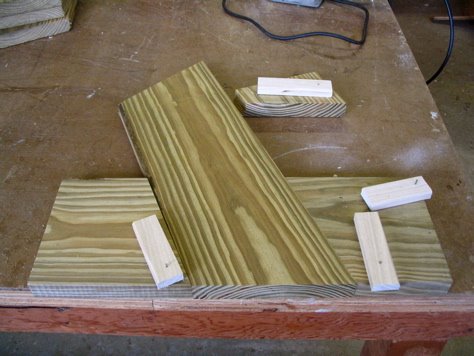
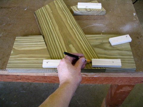
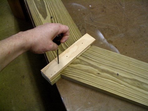
Once I had a pile of 40 base pieces, I needed to figure out a quick and dirty way to join them together. I decided I'd use biscuits, and I made the marking jig above to save myself from having to make 160 measurements (4 biscuits per piece x 40 pieces = 160 biscuits). The workpiece slid into the jig...


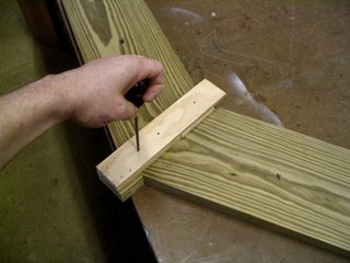
Then the poplar arms were swung until they were parallel to the end of the piece. I marked a line at the end of the swinging chaweeka.


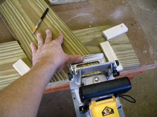
Then I cut the biscuit slots. By the way, when I say biscuits, I mean little ellipses of compressed wood that are inserted in matching slots to join together two pieces of wood. I do not mean the sorts of biscuits one eats. For the best edible biscuits in town, go to Perly's.


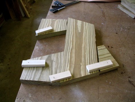
After biscuiting the left-hand ends of each piece, I followed the same procedures for the right-hand ends as you can see above.


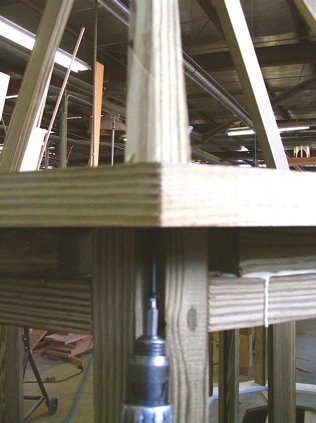
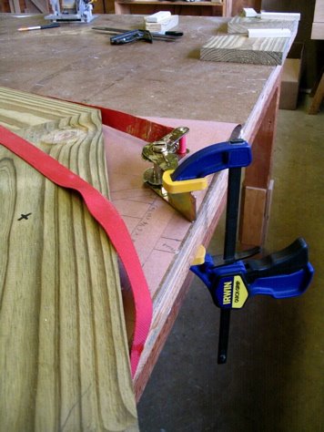
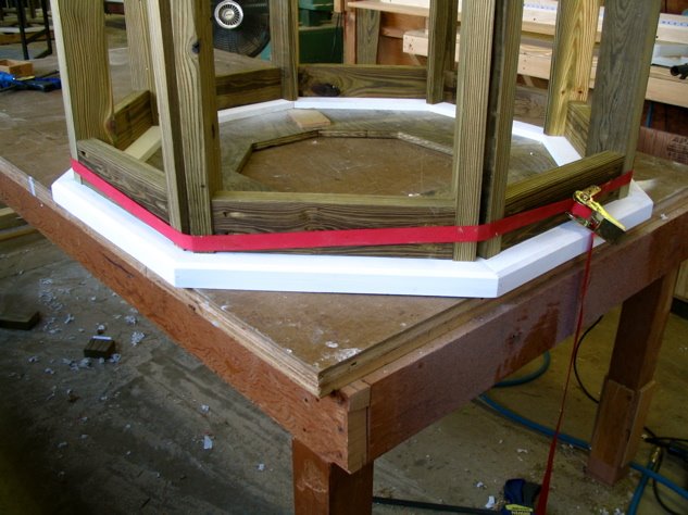
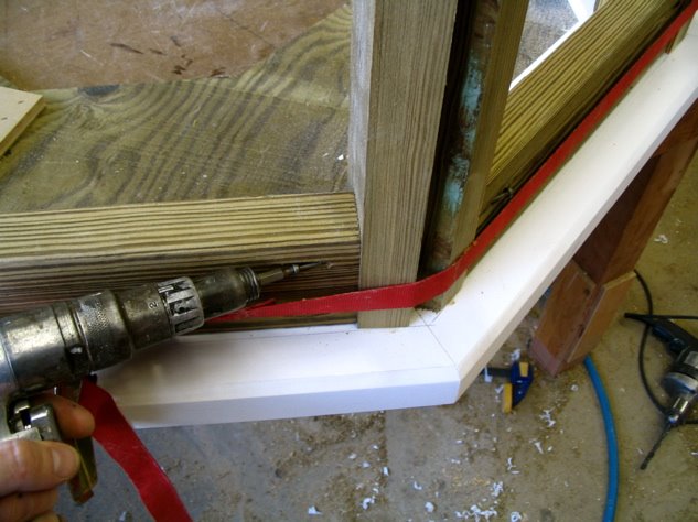
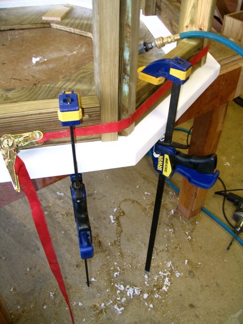
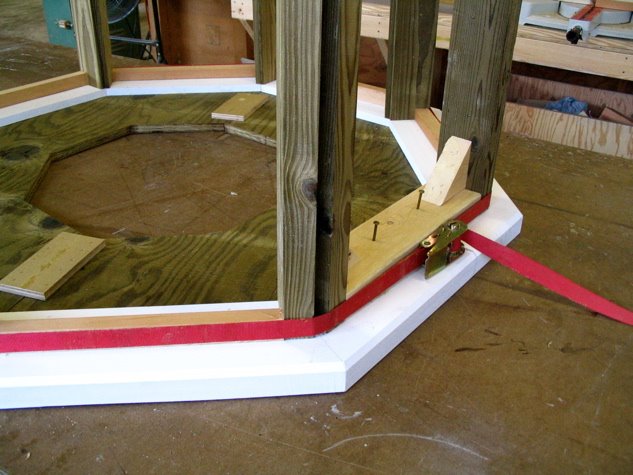
A coworker helped me glue the biscuits and put them in their slots. One has to work fast when dealing with this many wet biscuits; they swell up fairly quickly, reducing the open glue time one has before everything is set. I included the above picture because it depicts a solution to a problem that has long troubled me. As I've said before, I love band clamps. I particularly love them for clamping large mitered workpieces like these roof bases. One downside to band clamps, though, is that no matter how careful one is, they always seem to get twisted. I've been cussing about this for almost 15 years now, and it finally ocurred to me last week that if I thought about the problem for all of five minutes, I might be able so solve it. It's so obvious, really: Just clamp the ratchet mechanism to a table. Sheesh, I wish I'd started doing this a long time ago!


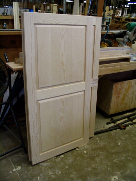
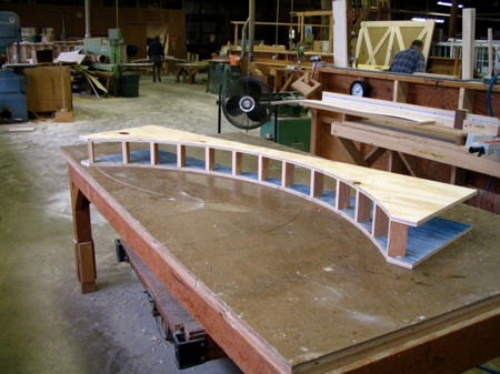
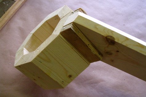
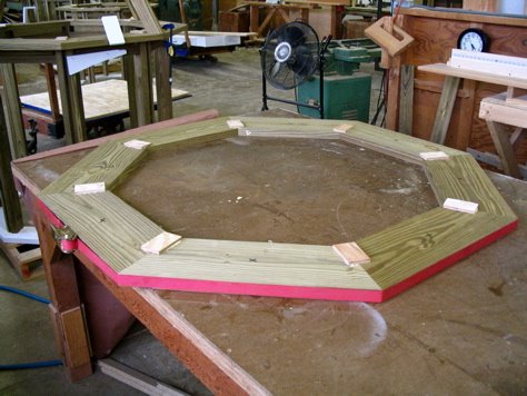
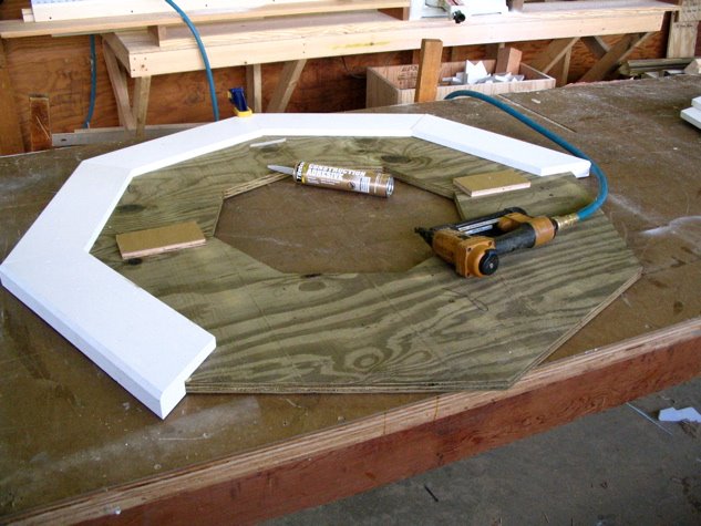
Here's the assembled roof base.


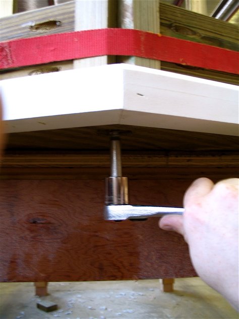
And here's a simple marking jig I put together to mark where I needed to drill holes.


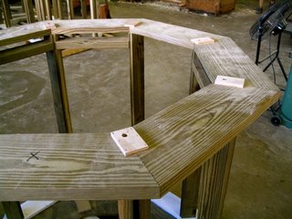
Finally, a completed roof base. I put the plywood scabs on to add tensile strength as well as to give the lag bolts that will eventually connect the roof to the cupola base something to bite down on.

Tomorrow I'll be posting about gnomes.

Sunday, October 08, 2006

I'm Tired of Cupolas!

I'm tired of thinking in multiples of eight. Enough octagons for a while. Here's a work table I made five or six years ago for the kitchen in my apartment. I wanted a "real" butcher block top, by which I mean one with the grain running top to bottom. All the old butcher blocks I've seen were made that way, I suppose because the harder end grain is more resistant to knife strikes. Apparently, the butcher would use his table all day, then at work's end, he'd pour scalding water on it and scrub it with a stiff wire brush. That's why all the old tables one sees in antique stores are so wallowed out in the center.


I don't know how I could have made this thing without Harrison's Time Saver sander. I started by making a bunch of 1.75" x 1.75" x 40" strips of hard maple, making sure they were dead square by running them through the sander on each face several times. I then glued four of these lengths together at a time resulting in a pile of 3.5" x 3.5" x 40" pieces. I cut these into 3.25" lengths, then glued six of them together to form a single row. Then I started gluing the rows together. Finally, I ran the whole thing through the Time Saver for what seemed like forever to get it nice and flat.


Big lesson learned while making this table: Use MINERAL oil to coat your butcher block if you ever decide to make one, not vegetable oil like I foolishly used. Oh, why didn't I spend half an hour doing research? Why? Why? Why did I spend that half an hour dousing $250 worth of maple endgrain with vegetable oil which quickly went ransid, creating a yucky film on the surface of this top? The poor thing isn't even close to suitable for kitchen use. It's holding my stereo and printer these days. So sad, yet so instructive.

Thursday, October 05, 2006

Cupola Base Framing Complete

I finished framing the cupola bases today. I had thought this task would be pretty easy, but it turned out to be a tad trickier than I'd anticipated. The first photo below shows one of the completed frames. You'll see that I'm building these things on pallets at this point as they're only going to get heavier over the next week or so until I'm finished. I imagine we'll have to move them out of the shop with forklifts once all is said and done.


My hope had been that by putting the correct length of spacer between each post and drawing the whole assembly together with a band clamp, everything would come out perfectly dimensioned. I still don't know exactly why it didn't work the way I'd planned, although I suspect there were minute (but additive) irregularities in the posts I had made. As you can see in the photo above, I did use the band-clamp strategy, and it did work--just not as smoothly as I'd hoped. Framing the first cupola base took four hours. The subsequent five only took an hour and a half apiece.


Once I'd gotten everyhing in its place, I attached the spacers to the posts with pocket hole screws. The spacers at the bottom were temporary, just placed there to assist in locating the posts. They did, however, serve another function; more on that later.


Screwing the spacers to the posts gave me a way to clamp the posts securely in place, as you can see above.


At the beginning of the week I had pre-drilled holes through the bottom of the bases. I made a simple jig on the drill press table to locate the holes. First I used a 1 1/2" forstener bit to make a hole deep enough to accomodate a lag bolt's head. Then I drilled a 1/2" hole through the center of the first hole. My jig kept the workpiece properly positioned so that all the holes were just where I wanted them.


Once I was positive that I had the post perfectly positioned, I located my drill by using the holes I had pre-drilled earlier in the week into the bottoms of the bases. I bored a deep 13/32" hole up through the base and into each post.


Then I drove long lag bolts through the bottom. I can't stress enough how much I very, very much want these things to stay in one piece when they're being lifted 30 or 40 feet in the air by a crane. That's why I'm incorporating just about every over-building idea I can think of!


Here are the first few base frames sitting in the shop. At this point, I'm moving them around with a pallet jack.

Oh, one last thing: Remember the spacers I'd used to locate the posts? I used those same pieces as the headers between the tops of the posts. That way I could be certain that the interior widths of the frames between each post would share the same dimension top and bottom.

Monday, October 02, 2006

Woodworking Wisdom from Cormac McCarthy

Have you ever noticed how bull-headed so many woodworkers are? Why is that? Why is it that once we've done something the same way once or twice we usually stop looking for ways to improve our technique? Maybe it's what psychologists call "functional fixedness." I don't know. A related thing I've noticed is that many of us are loath to let it show when we're seeing somebody else doing something we didn't know about.

To that end, check out the following quote from Cormac McCarthy's All the Pretty Horses. My wife is reading it right now, and she emailed this to me today.

"They listened with great attention as John Grady answered their questions and they nodded solemnly and they were careful of their demeanor that they not be thought to have opinions on what they heard for like most men skilled at their work they were scornful of any least suggestion of knowing anything not learned at first hand."

Tiny Cupola Roofs

I started the day a tad perplexed about how to proceed with the construction of the cupolas' roofs, so I spent some time making quarter-scale models. I think I pretty much figured out how I want to do it.


The framing structure will basically consist of 8 pressure-treated 2 x 4s which will all meet a central octagonal shaft. There will be all manner of bracing, as well, but the photo above shows just the bare-bones of my plan. I rarely take the time to make models, but they help me when I'm really confused. I saved myself a lot of grief by making this one. If I hadn't, I'd have forgotten that the thickness of the PVC sheathing is greater than 3/4" when on a bias. That would have been a BIG BUMMER as it would have resulted in the roofs overhanging more than they're supposed to.


Here's the model for the roofs' sheathing. You can see where I made notes all over it to correct problems. One major benefit of making this model was that it helped me to figure out the jigs I'll need to get the correct bevels in the right places. I haven't done a cone-shaped thing in a quite a while, so this was a helpful exercise.

Saturday, September 30, 2006

Cupola Framing Starts

Here's a section view of the cupola's vertical framing members. Each one consists of two lengths of pressure-treated 2x4 beveled at 22 1/2 degrees then glued and stapled together.


In general, I like to take measurements from assembled workpieces. By doing so, I can always test what is rather than what ought to be. In this case, I dry-assembled the vertical framing members in place on the sill so I could find the exact distance between them. Next week I'll be making louvers that fit in the spaces between the vertical members. The outside dimensions of the louver frames will have to fit just about perfectly, so I took plenty of time getting this dry assembly just right.


One of my coworkers, Wayne, saw the framing members standing upright on the sill and wondered if I was using some kind of mental telepathy to make them stand up so straight. In fact, they're just squeezed together with a band clamp and spacer sticks. I love band clamps; when assembling frames, there's nothing better because they automatically distribute any minute error equally across all the joints. Plus, they're relatively inexpensive.

Friday, September 29, 2006

Set of Five Massive Cupolas Begun


Here is a part of the final drawing for the cupolas. Our shop has a full-time draughftsman who produces these. We also have the ability to print full-size drawings of any element within the overall drawing. Sometimes I glue full-size drawings to a piece of 1/4" material for use as a tracing or routing template.

The cupolas are huge; roughly 7' tall by nearly 5' wide at the underside of the roof. They're going on an old school in Richmond's east end and are near-exact reproductions of the original cupolas which have rotted away to nearly nothing.

My first step was to make pressure-treated plywood bases upon which everything else would be built. To do this, I cut 1/8 of the octagon size I needed from a scrap of ply. Then I traced that piece four times onto the piece of scrap 1/2" MDO you see above. I trimmed the resulting template on the bandsaw, then perfected the lines with a straight edge and router.

Whenever I make templates, I like to make one half of the final size I require. See how the template is marked for right-sidedness? I traced five of the pressure-treated ply halves with that side facing up and five with the reverse side up. That way, any minute imperfections in the template are mirrored side-to-side.


Here are the five pressure-treated ply bases. I used the template to flush-trim the halves on the router table. The halves are joined together with #20 biscuits and the 1/2" ply scabs you see in the photo.

The sill that wraps around the ply bases has several parts. The lowest section is depicted above. It, like much of this project, is made from PVC. We can't get 1 1/2" thich PVC for some reason, so I had to laminate two 1 x 6's together to get the stock I needed. We used a shaper to create the rabbet and the router table to make the bevel. No big deal, but when you're making five octagons, you need 40 of each part you make (8 sides x 5 octagons = 40). By the way, yes, the bevel is a little crooked on the above piece, but happily, PVC dresses very neatly with a block plane.


Here the sill elements are attached to the ply bases. I used construction adhesive and long staples. I worry that any fasteners I use will eventually rust away to nothing, so I'm using some kind of adhesive whenever feasible.