Saturday, September 30, 2006

Cupola Framing Starts

Here's a section view of the cupola's vertical framing members. Each one consists of two lengths of pressure-treated 2x4 beveled at 22 1/2 degrees then glued and stapled together.


In general, I like to take measurements from assembled workpieces. By doing so, I can always test what is rather than what ought to be. In this case, I dry-assembled the vertical framing members in place on the sill so I could find the exact distance between them. Next week I'll be making louvers that fit in the spaces between the vertical members. The outside dimensions of the louver frames will have to fit just about perfectly, so I took plenty of time getting this dry assembly just right.


One of my coworkers, Wayne, saw the framing members standing upright on the sill and wondered if I was using some kind of mental telepathy to make them stand up so straight. In fact, they're just squeezed together with a band clamp and spacer sticks. I love band clamps; when assembling frames, there's nothing better because they automatically distribute any minute error equally across all the joints. Plus, they're relatively inexpensive.

Friday, September 29, 2006

Set of Five Massive Cupolas Begun


Here is a part of the final drawing for the cupolas. Our shop has a full-time draughftsman who produces these. We also have the ability to print full-size drawings of any element within the overall drawing. Sometimes I glue full-size drawings to a piece of 1/4" material for use as a tracing or routing template.

The cupolas are huge; roughly 7' tall by nearly 5' wide at the underside of the roof. They're going on an old school in Richmond's east end and are near-exact reproductions of the original cupolas which have rotted away to nearly nothing.

My first step was to make pressure-treated plywood bases upon which everything else would be built. To do this, I cut 1/8 of the octagon size I needed from a scrap of ply. Then I traced that piece four times onto the piece of scrap 1/2" MDO you see above. I trimmed the resulting template on the bandsaw, then perfected the lines with a straight edge and router.

Whenever I make templates, I like to make one half of the final size I require. See how the template is marked for right-sidedness? I traced five of the pressure-treated ply halves with that side facing up and five with the reverse side up. That way, any minute imperfections in the template are mirrored side-to-side.


Here are the five pressure-treated ply bases. I used the template to flush-trim the halves on the router table. The halves are joined together with #20 biscuits and the 1/2" ply scabs you see in the photo.

The sill that wraps around the ply bases has several parts. The lowest section is depicted above. It, like much of this project, is made from PVC. We can't get 1 1/2" thich PVC for some reason, so I had to laminate two 1 x 6's together to get the stock I needed. We used a shaper to create the rabbet and the router table to make the bevel. No big deal, but when you're making five octagons, you need 40 of each part you make (8 sides x 5 octagons = 40). By the way, yes, the bevel is a little crooked on the above piece, but happily, PVC dresses very neatly with a block plane.


Here the sill elements are attached to the ply bases. I used construction adhesive and long staples. I worry that any fasteners I use will eventually rust away to nothing, so I'm using some kind of adhesive whenever feasible.


Various Past Projects


This yellow pine bookcase features saw tooth supports. You can catch a glimpse of them in the case's right-hand rear corner. This case is very tall, and just barely tips upright below an 8' ceiling.

I made this wenge butler's tray as a wedding present for my friends Jamie and Michaelann. I like the idea of using an exotic wood for such a stodgy, traditional form. The corner joints are dovetails with a mitered top.


This is the first piece I ever designed and built for myself. I'm sitting at this writing table right now, as a matter of fact.


Okay, you either love it or hate it. I made this toy chest for my niece's first birthday. It was a faux-finishing learning exercise, really. My good friend Stuart Bailey taught me the technique--it's meant to look like it's tiled with pieces of malachite.

Broken Pediment Entrance Head


I finished this broken-pediment PVC entrance head a few weeks ago. Getting it just right was kind of involved because of the many compound angles in the various mouldings.


This detail shows the various runs of moulding. We recently started using a new kind of modillion block--they're actually made of a hard, blown styrofoam which is a tad depressing, I think. Oh well. For the dentil mouldings along the rake, I made individual teeth and spaced them with a spacer block rather than routing them or finding some way to use a dado cutter.

Pembroke Table


I began work on this federal Pembroke table in the early spring of 1999. It is a close reproduction of a table from the Kaufman collection, a private collection of American furniture exhibited at the National Gallery of Art in 1986 and catalogued in American Furniture From the Kaufman Collection by J. Michael Flanigan.


The table's serpentine top is characteristic of New York pembroke tables.


The drawer is pulled from the underside so that it appears to just be an apron. I love hidden things like that. The drawer face is veneered with crotch mahogany. Other inlaid elements include boxwood and ebony stringing as well as satinwood panels. The original table had urn and swag details where I put the satinwood. Urns and swags are a bit fussy for my tastes.


This photo details what I was talking about with the drawer. It also shows the many bandings that follow the perimeter of the serpentine top. To get the boxwood and ebony to bend along the tight corner radius, I soaked them, then gently bent them around a guitar side-bending iron.

Ram's Head Mantel & Paneling Finished

Here are a couple of photos of the large mantel I finished in July. I built it in three sections; 1) the mantel shelf and legs, 2) the frame and panel element, and 3) the moulded ram's head.

By far the trickiest part of this project was getting all the miters right on the ram's head. I like to use templates for that kind of thing. That way I can get my thinking straight and mistakes corrected on scrap pieces rather than on an actual workpiece with a couple of hours of work in it.


The photo below shows the entire structure. To give you a sense of how tall the finished piece was, I had to get up on a 16' ladder to get the whole thing in my camera's frame.

Chop Saw Setup Complete!

I finished my chop saw setup a few weeks ago, and am finally getting around to posting about it. This Hitachi saw was a freebie from one of our shop's suppliers. It sat next to the break table for about six weeks before I finally claimed it for my work area.

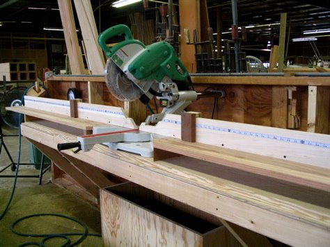
Here's the finished set up in all its glory. There are several problems with normal chop saw arrangements that I wanted to correct. The first was drooping table extensions. I hate it when you have to apply significant downward pressure on your workpiece to keep it square. The second problem was always having to use a measuring tape and pencil every time you want to make an accurate cut. The third problem was coming up with a stop system that was versatile and did not require any clamps. More below.


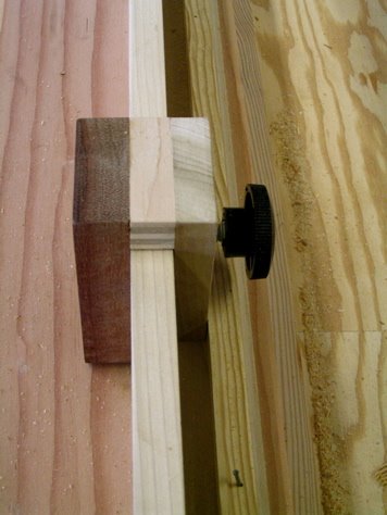
Here's the stop I came up with. It slides along the fences and clamps with a threaded knob along the back. I was naive in thinking that the threaded bolt would hold the thing square; all it did was spread the bottom of the front side of the stop away from the fence. That's why you see a nailed-on pine strip underneath the knob. It keeps the bolt's pressure correctly oriented.


Each side of the fence has its own stop, and each stop has two square sides. One side of each is relieved to allow dust, while the other is left straight all the way to the table. This way, if I'm ever crosscutting veneer or other really thin stock, I can use the straight side.

I attached tapes to 1/4" thick strips of poplar and fit them into dadoes I routed into the fences. This way, I can set the edge of the stops at any dimension along the fence and cut accurately. No need to measure! I found left-reading and right-reading metal, adhesive-backed tapes at Woodcraft.

Another thing you can see in this picture is part of the system I used for leveling the tables. Both tables are attached to two cherry strips like you see below. The strips have threaded inserts about halfway down their lengths that accept a bolt through the middle of the tabletop. A few inches on either side of that bolt, the top has threaded inserts with set screws in them. Leaving the middle bolt loose, I adjusted the set screws using a laser level on the tables until they were perfectly level from far left, across the saw, out to far right. That took a lot of work. Once it was done, I socked down the bolts in the center. If the table sags in the future (which it probably will), I'll just adjust again.


I figured that I'd never get the tapes perfect if I stuck them directly onto the fences. That's why I went with the inlaid strips. To allow me to perfectly index the tapes, I used the system of elongated holes above. It took a bit of fiddling, but the tapes and stops now work together well enough that I can cut any length accurately to within 1/64th.


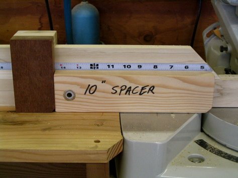
Because of the saw's built-in fences, the stops can't reach past 10" from the cut. So I came up with the spacer block you see above. If I have to cut something that's 2 1/4", I set the stop at 12 1/4", and add the spacer. I've found other uses for it, too. For instance, let's say I want to accurately cut 1/16" from the ends of a bunch of boards that aren't starting out at the same length. What I do is set up the stop and the spacer to the left of the cut so that the spacer is 1/16" shy of the right side of the kerf. I then butt my workpiece against the spacer, remove the spacer, and cut.


Here's a head-first shot. You can see where I wasted away the fences to allow for all possible compound bevels.
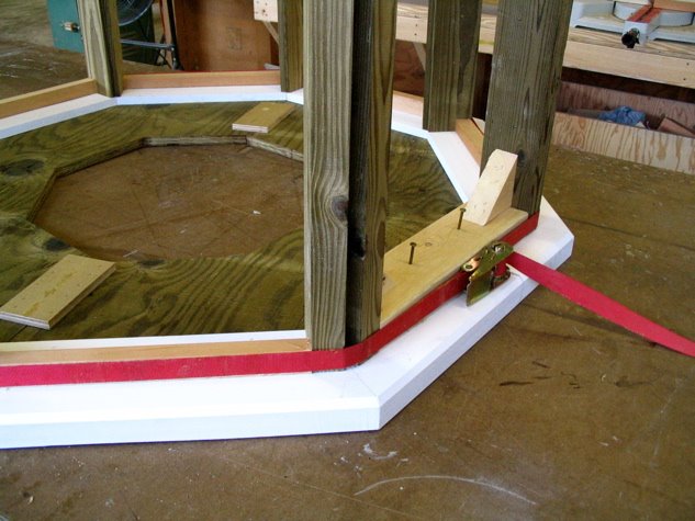
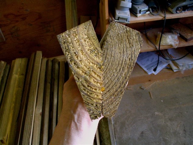